Reduce energy costs through power factor correction
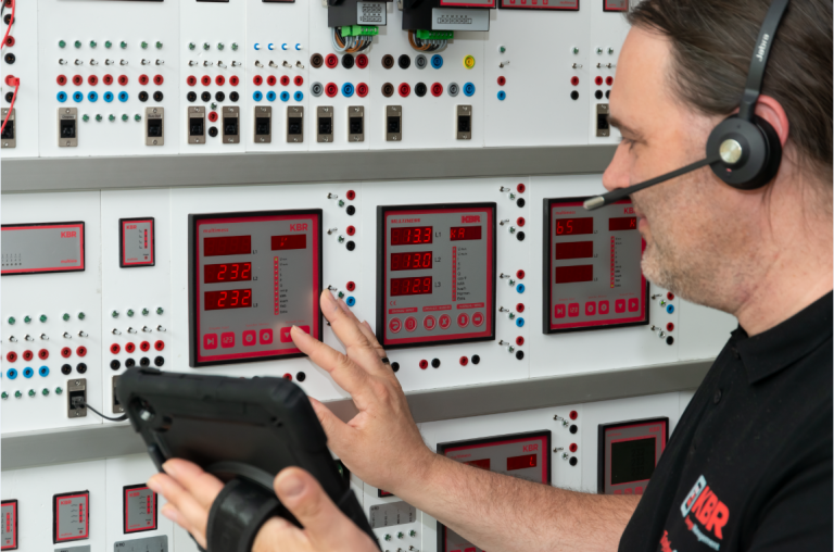
Our components provide you with everything you need to build your own durable, high-quality compensation system. Reactive power regulators, capacitors, filter circuit chokes or prefabricated compensation modules – all manufactured in our factory in Schwabach.
Savings of
Energy costs and Co2
Durability and quality
"Made in Germany"
Type-tested
Quality components
Thanks to our in-house development and production of components for power factor correction, we have achieved maximum durability and quality. Our experienced specialists in Schwabach carefully manufacture each individual component and then subject it to a comprehensive quality check.
With the individual capacitor modules and the control module, you can assemble your power factor correction system yourself quickly and easily in just a few steps. For maximum convenience, we also offer prefabricated power factor correction systems that are fully assembled and tailored to your specific requirements.
You can find instructions here: Installation instructions (PDF).


Subscribe to our newsletter mailing list. This will keep you up-to-date on our products and services.
Further information can be found in our privacy policy.
KBR Kompensationsanlagenbau GmbH
Am Kiefernschlag 7
91126 Schwabach
Modern energy management
More than ever before, the way energy is used is crucial to a company’s success.
At the same time, energy management is becoming increasingly important.
KBR’s products and solutions are fundamental here.

ISO 9001, ISO 14001 and ISO 50001