Search
Thyristor switch for reactive power compensation

thyroswitch

Reactive power compensation components
VO2 3217VO2 3214

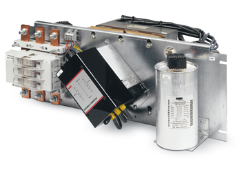
The thyroswitch thyristor switches enable reactive current compensation almost in real time.

Due to its unlimited switching frequency and minimal switching delay, the thyroswitch switches choked and unchoked capacitors on and off quickly and wear-free. When the capacitors are switched on in a controlled manner, no switch-on current peaks occur and the switching contacts do not wear out. This reduces the load on the capacitors, which in turn leads to a longer service life. In addition, the device operates silently and is characterized by its compact, ready-to-connect design. This results in significant advantages over conventional standard contactors.

The thyristor switch is available in both 2-phase and 3-phase versions. The thyroswitch is controlled via the multicomp reactive power controller or directly via the machine controller. If the switch-on process is activated via a reactive power controller or a control unit, a voltage comparison is made between the capacitor voltage and the mains voltage. If the difference is small, the stage is switched on.

The 2-phase thyristor switch thyroswitch 2P has two thyristors that switch phases L1 and L3. Phase L2 is connected but not switched.

The 3-phase thyristor switch thyroswitch 3P has three thyristors, each of which can switch individually or together.

Highlights
Technical details (2P)
Technical details (3P)
  • Unlimited switching frequency without loading the capacitors
  • No inrush current peak when switching on the capacitors
  • Low switching delay
  • Compensation almost in real time
  • No switching noises

Entrance
Control input:
10 – 30 V DC | max. 30 mA
180 – 260 V AC | 50 / 60 Hz | max. 20 mA
Protection: max. 6 A
Power supply
Auxiliary voltage: 230 V AC | 50/60Hz | max. 18VA
Protection:
max. 6 A
Load circuit
Supply voltageUN: 400/500 V | 50/60 Hz (depending on type p table)
Load current: 70/90/115 A (depending on type p table)
Power loss: 70 A type approx. 2.2 W per A
90/115 A type approx. 2.1 W per A
Field of application
Creepage distances from control input to power circuit: > 10.5 mm for SELV voltages
Nominal voltage: UN ± 10 %
Harmonic voltage: DINEN 61000-2-4 Class 3 | THD Max. 10 %
Switch-on delay Switch-off time > 5s
Entrance: DC: 0 to max. 20 ms
AC: 10 to max. 30 ms
Switch-on delay: Cyclical operation
Entrance: DC: 0 to max. 33 ms
AC: 10 to max. 43 ms
Electronic security : Standards and subsequent authorizations
Protection class: I
Distances: EN61010:2001 for pollution degree II
Measurement category III
Protection class: IP 10
Ambient conditions
Standards and subsequent corrections: DIN EN 60721-3-3/A2
(3K5 + 3Z11)
EC 721-3-3 (3K5 + 3Z11)
Humidity; non-condensing: 5 % to 95 %
Operating temperature: -5 °C to +55 °C – Note the power limitation depending on the ambient temperature.
Storage temperature -25 °C to +70 °C
Installation
Installation position: Vertical or horizontal
Cooling distances: min. 50 mm to the fan and min. 150 mm to the heat sink outlet
Housing
Dimensions in mm (H x W x D): 220 x 105 x 185 mm
220 x 105 x 198 mm (type / type 115 A)
Weight
approx. 2900 g
approx. 3600 g (type / type 115 A)
Entrance
Control input: 10 – 30 V DC | 3 inputs each max. 30 mA
Protection: max. 6 A
Power supply
Auxiliary voltage: 230 V AC ± 10 % | 50 / 60 Hz | max. 35 VA
Protection:
max. 6 A
Load circuit
Supply voltageUN: Δ 400 V / 50 Hz | Υ 690 V / 50 Hz
Load current: max. 100 A
Power loss: 70 A type approx. 3 x 1.1 W per A
100 A type approx. 3 x 1.05 W per A
Field of application
Creepage distances from control input to power circuit: > 10.5 mm for SELV voltages
Nominal voltage: UN ± 10 %
Harmonic voltage: DINEN 61000-2-4 Class 3 | THD Max. 10 %
Switch-on delay Switch-off time > 5s
Entrance: 0 to max. 20 ms
Switch-on delay : Cyclical operation
Entrance:
0 to max. 33 ms
Electrical safety: standards and subsequent corrections
Protection class: I
Distances: EN61010:2001 for pollution degree II
Measurement category III
Protection class: IP 10
Ambient conditions
Standards and subsequent corrections: DIN EN 60721-3-3/A2
(3K5 + 3Z11)
EC 721-3-3 (3K5 + 3Z11)
Humidity; non-condensing: 5 % to 95 %
Operating temperature: -5 °C to +55 °C
Installation
Installation position: Vertical or horizontal
Cooling distances:
min. 50 mm to the fan and min. 150 mm to the heat sink outlet
Housing and weight
Dimensions in mm (H x W x D): 220 x 182 x 188 mm
Weight approx. 5800 g
Fittingly:
multimod-f_050_01-1000-14-08tb_

Built-in module with thyristors

multicab-r_thyro_open-closed-multicomp_

Power factor correction system with thyristor switch

KBR
Support Team

We are happy to arrange
the contact to our
references and are available for
available for an interview.

Just get in touch with us.
Phone: +49 9122 6373-0
E-mail: info@kbr.de

Tablet mit Screenshot

Download

More information (brochures, user manuals, etc.) under download.