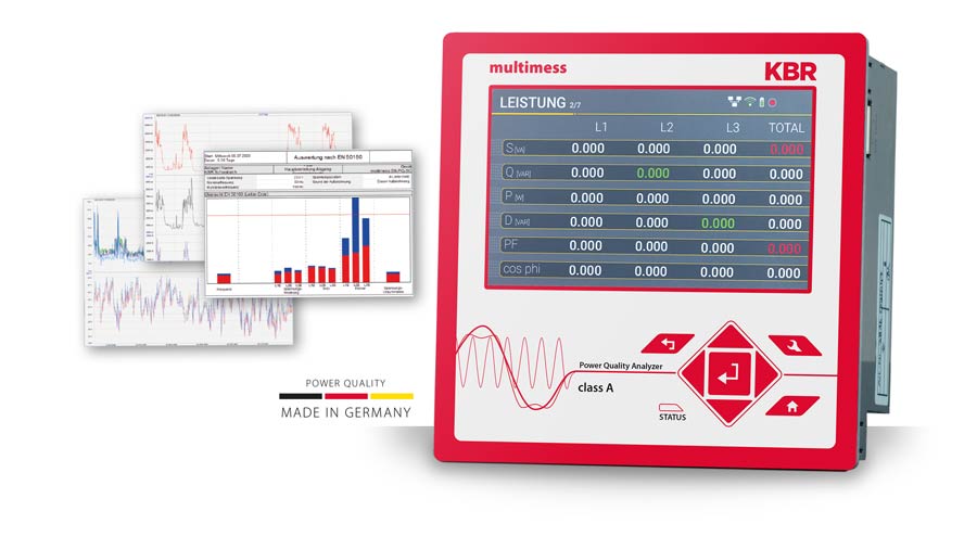
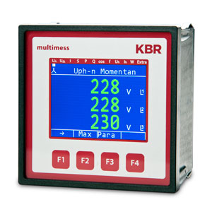
multimess F144 power meter
| Device types overview |
|
|
Article no.
US1 |
Article no.
US5
(optional)
|
Article no.
US1-NRTL |
| [1] |
multimess F144-0-LED-EP-2RO1DO-US_ |
24007 |
24008 |
24014 |
| [2] |
multimess F144-2-LED-ESMS-2RO1DO-US_ |
23654 |
23659 |
23883 |
| [3] |
multimess F144-2-LED-ESMSET-2RO1DO-US_ |
23655 |
23660 |
23884 |
| [4] |
multimess F144-2-LED-ESMSMT-2RO1DO-US_ |
23656 |
23661 |
23885 |
| [5] |
multimess F144-2-LED-ESMSDP-2RO1DO-US_ |
23657 |
23662 |
– |
| [6] |
multimess F144-2-LED-ESMS-2RO1DO3AO-US_ |
22809 |
23666 |
23886 |
| [7] |
multimess F144-2-LED-ESMSET-2RO1DO3AO-US_ |
23663 |
23667 |
23887 |
| [8] |
multimess F144-2-LED-ESMSMT-2RO1DO3AO-US_ |
23664 |
23668 |
23888 |
| [9] |
multimess F144-2-LED-ESMSDP-2RO1DO3AO-US_ |
23665 |
23669 |
– |
US1: 100 bis240 V +/- 10% AC/DC 50/60 Hz, 18 VA, 10 W
US5 (optional): 22,5 bis 64 V +/- 10% AC/DC 50/60 Hz, 15 VA, 10 W
| Input and output configuration |
| Device types |
[1] |
[2] |
[3] |
[4] |
[5] |
[6] |
[7] |
[8] |
[9] |
Digital inputs
1 synchronization,
1 HT/NT tariff |
– |
Yes |
Yes |
Yes |
Yes |
Yes |
Yes |
Yes |
Yes |
| Pulse output (P+/Q+) |
1 |
– |
– |
– |
– |
– |
– |
– |
– |
| Pulse output (P+/Q+/P-/Q-) |
–
|
1
|
1
|
1
|
1
|
1
|
1
|
1
|
1
|
| Relay output |
21 |
21, 2 |
21, 2 |
21, 2 |
21, 2 |
21, 2 |
21, 2 |
21, 2 |
21, 2 |
| Analog outputs |
– |
– |
– |
– |
– |
3 |
3 |
3 |
3 |
| Interface |
– |
RS485 |
RS485 |
RS485 |
RS485 |
RS485 |
RS485 |
RS485 |
RS485 |
| KBR eBus |
– |
Yes |
Yes |
Yes |
Yes |
Yes |
Yes |
Yes |
Yes |
| KBR eBus TCP |
– |
|
Yes |
– |
– |
– |
Yes |
– |
– |
| Modbus RTU/ASCII |
– |
Yes |
Yes |
Yes |
Yes |
Yes |
Yes |
Yes |
Yes |
| Modbus-TCP |
– |
|
– |
Yes |
– |
– |
– |
Yes |
|
| Profibus-DP |
– |
– |
– |
– |
Yes |
– |
– |
– |
Yes |
| Power supply |
US1: 100 bis240 V +/- 10% AC/DC 50/60 Hz, 18 VA, 10 W |
|
US5 (optional): 22,5 bis 64 V +/- 10% AC/DC 50/60 Hz, 15 VA, 10 W |
1 Limit function
2 Additional switching reality function via bus
Details, metrics and storage – [1]
| Details, metrics and storage |
|
multimess F144-0-LED-…
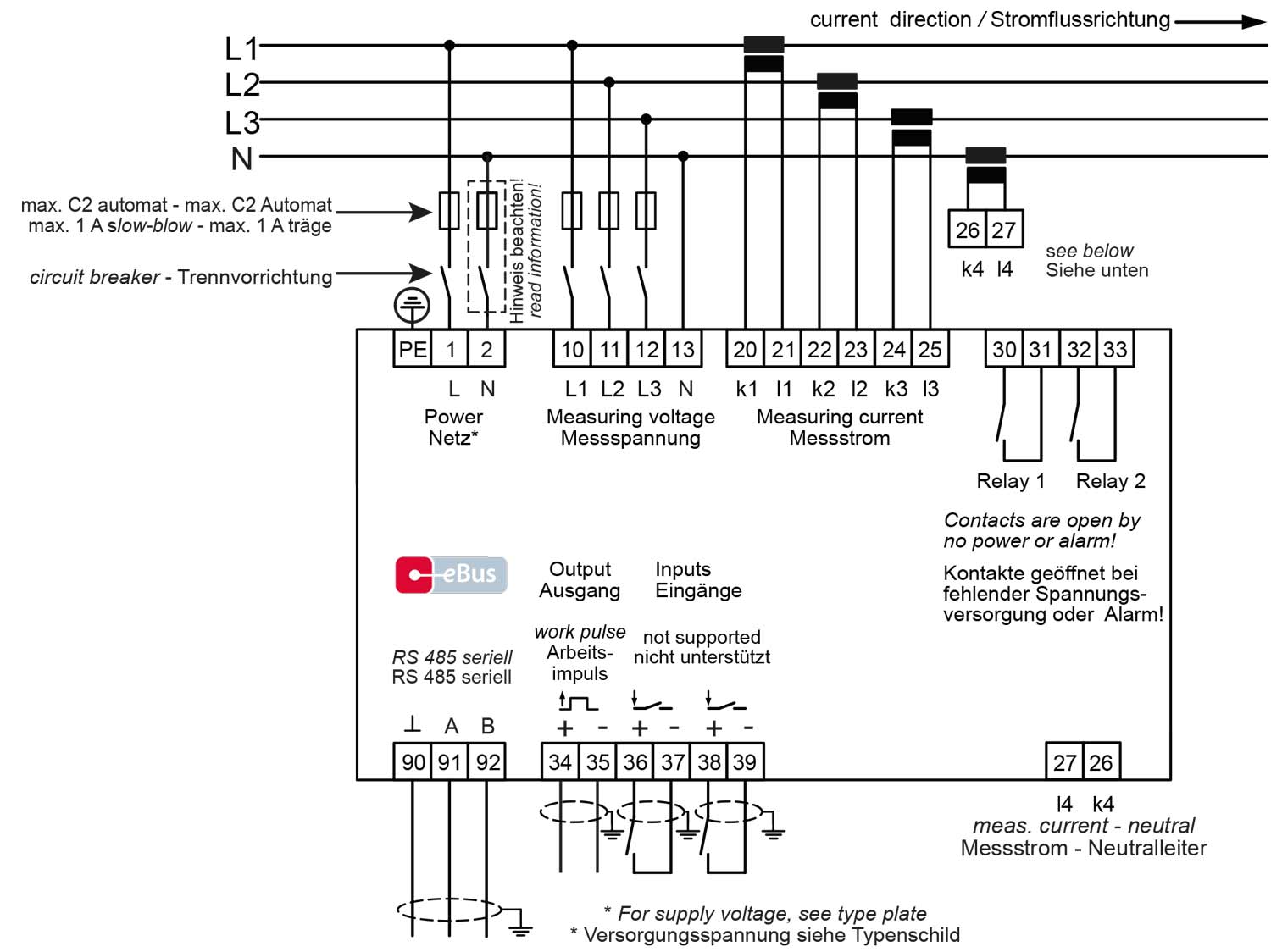
[1] …EP-2RO1DO-US_ |
| Metrics |
| Tension |
U Ph–N (L1 – L3) | U Ph-Ph |
| Electricity |
I Ph (L1 – L3) |
| Average current value |
I Ph (L1 – L3) |
| Neutral conductor current |
IN | IN means |
| Apparent power |
S Ph (L1 – L3) | S total |
| Active power |
P Ph (L1 – L3) | P total |
| Q1 = fundamental reactive power |
Q1 (L1 – L3) | Q 1 total |
| Frequency |
f network |
| Harmonics |
THD (L1 – L3) voltage |
| Rotating field control: rotating field display in degrees |
Yes |
| Performance factors |
Fundamental oscillation cosφ (L1 – L3) |
|
Total power factor λ (L1 – L3) | λ total |
| Electrical work |
Endless counter for active work P+ |
|
Endless counter for blind work Q+ |
| Tariff switchable |
HT / NT |
| Memory |
| Load profile memory P total / Q total |
– |
|
– |
Storage duration of the load profiles
(with a 15 minute measurement period) |
– |
| Daytime, active and blind work |
– |
| Split pointer function (min. / max.) |
For all displayed measured values, Wir-2 and reactive power period 2 with date and time |
| Event memory |
– |
| Operational diary |
– |
2 Maximum value only
Details, metrics and storage – Device type[2]to[9]
| Details, metrics and storage |
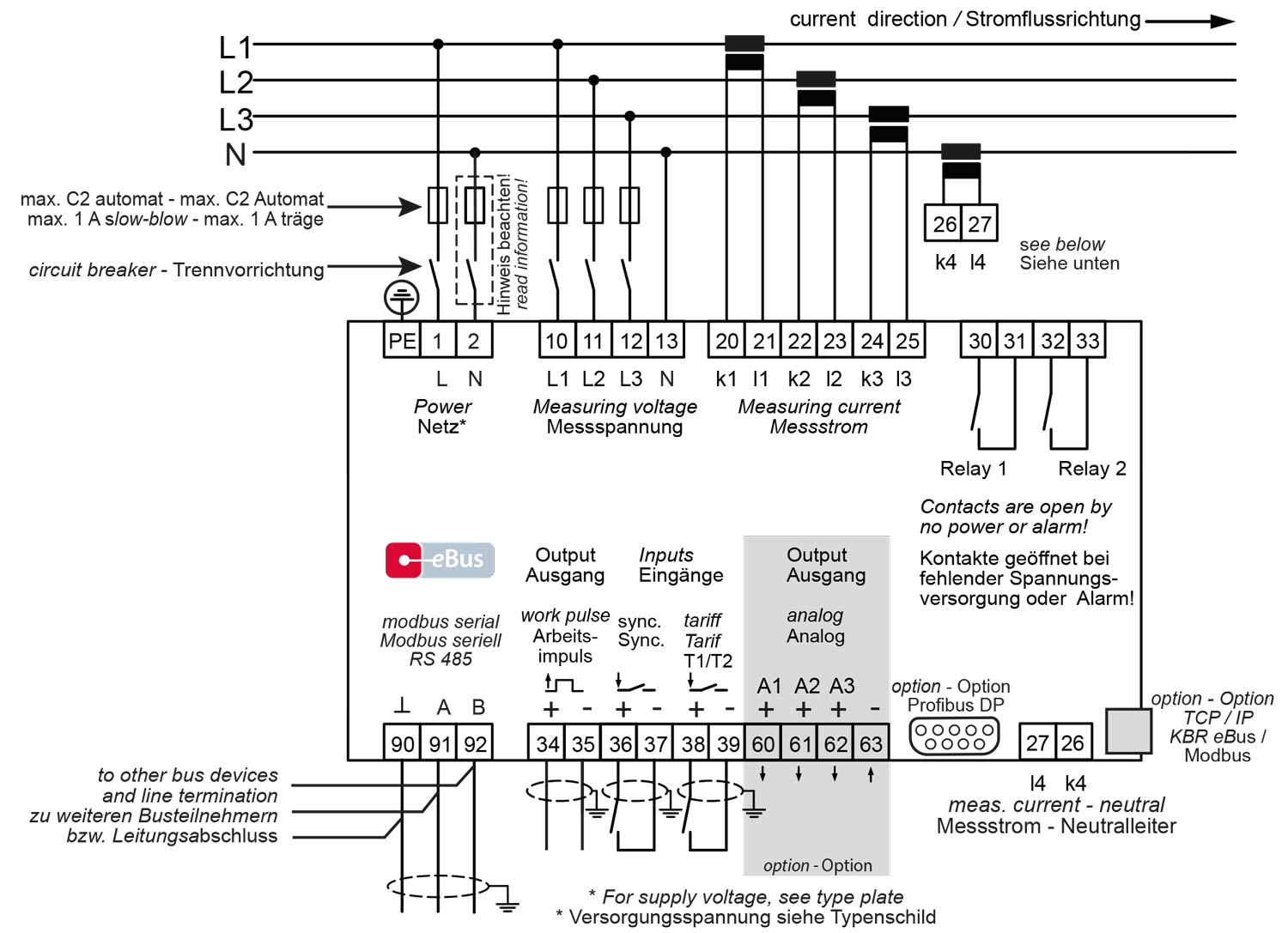
| multimess F144-2-LED-…
[2] …ESMS-2RO1DO-US_
[3] …ESMSET-2RO1DO-US_
[4] …ESMSMT-2RO1DO-US_
[5] …ESMSDP-2RO1DO-US_ |
multimess F144-2-LED-… (with 3 analog outputs)
[6] …ESMS-2RO1DO3AO-US_
[7] …ESMSET-2RO1DO3AO-US_
[8] …ESMSMT-2RO1DO3AO-US_
[9] …ESMSDP-2RO1DO3AO-US_ |
| Metrics |
| Tension |
U Ph–N (L1 – L3) | U Ph-Ph |
| Electricity |
I Ph (L1 – L3) |
| Average current value |
I Ph (L1 – L3) |
| Neutral conductor current |
IN | IN-average |
| Apparent power |
S Ph (L1 – L3) | S total |
| Active power |
P Ph (L1 – L3) | P total |
| Q1 = fundamental reactive power |
Q1 (L1 – L3) | Q 1 total |
| Frequency |
f network |
| Harmonics |
THD (L1 – L3) voltage |
|
THD (L1 – L3) current |
|
3rd – 63th Harm. (L1 – L3) Tension |
|
3rd – 63th Harm. (L1 – L3) Electricity |
| Rotating field control: rotating field display in degrees |
Yes |
| Performance factors |
Fundamental oscillation cosφ (L1 – L3) |
|
Total power factor λ (L1 – L3) | λ total |
| Electrical work |
Endless counter for active work P+ | P- |
|
Endless counter for blind work Q+ | Q- |
| Tariff switchable |
HT / NT |
| Memory |
| Load profile memory P total / Q total |
P+1 | Q+1 (cumulative) |
|
P-1 | Q-1 (cumulative) |
Storage duration of the load profiles
(with a 15 minute measurement period) |
Ring memory for 366 days |
| Daytime, active and blind work |
Annual working memory, daily values for active and reactive work 1 |
| Split pointer function (min. / max.) |
For all displayed measured values, Wir-2 and reactive power period 2 with date and time |
| Event memory |
1500 events with date, time and duration, e.g. Limit values exceeded and undershot, power failures and voltage increases ≥ 20 ms at 100% measurement voltage drop 1 |
| Operational diary |
500 entries with date and time 1 |
1 Only available via the interface
2 Maximum value only