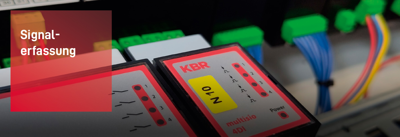
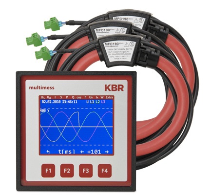
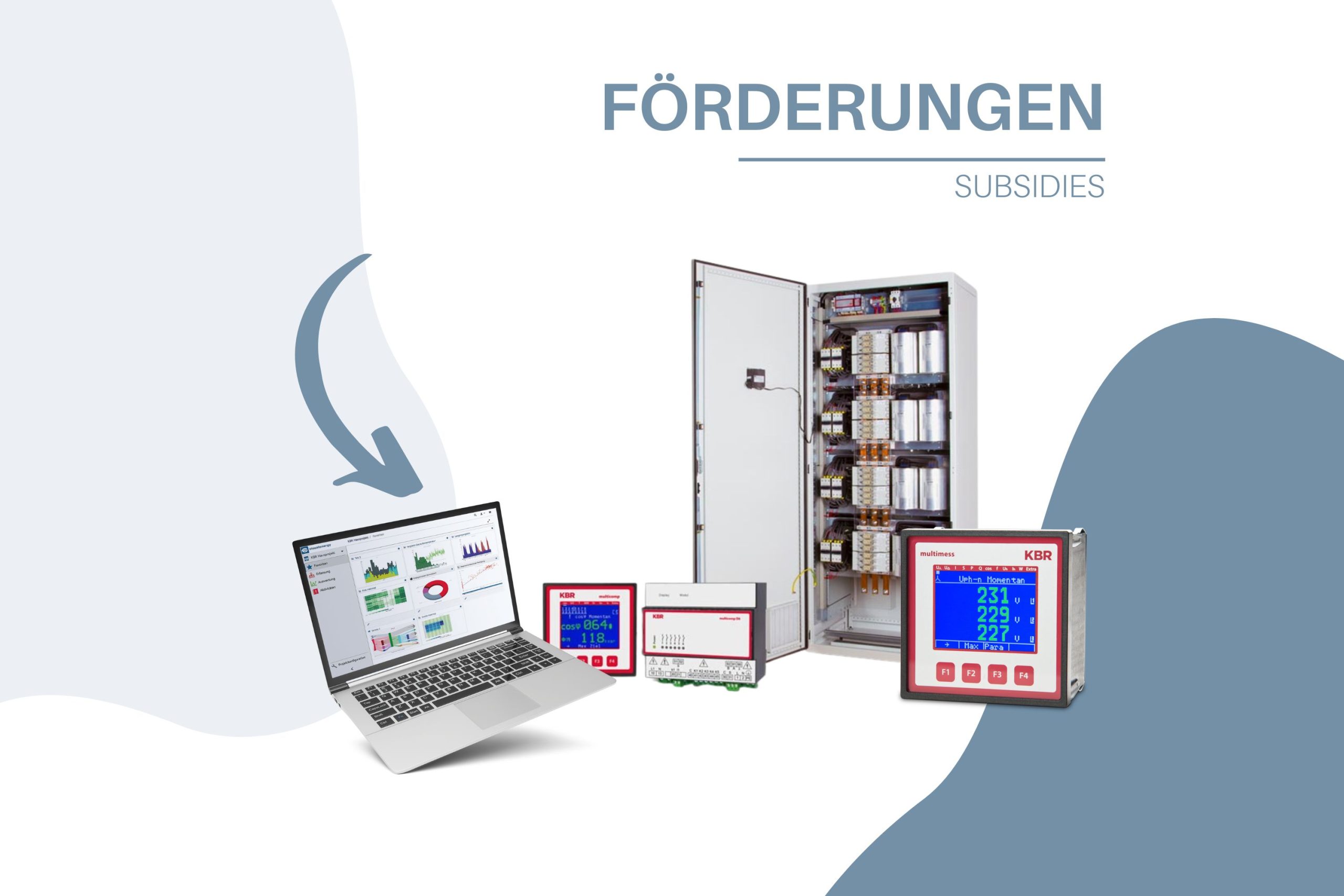
Electronic network measuring device
The electronic network measuring devices in the multimess F96-TFT series offer comprehensive measurement and monitoring of all important parameters in the three-phase three-phase network and are available in various versions.
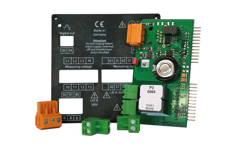
A pulse output is integrated in all devices. Load profile storage (P+ P- / Q+ Q-) is available on all models except the entry-level device F96-0 and can be read out via the eBus. You can also monitor the mains voltage in accordance with EN 61000-4-30 and the voltage and current curve is saved in the event of a deviation.
You can analyze this data directly on the TFT display. Various optional interfaces and protocols allow the devices to be used in a variety of ways.
Information on the interfaces:
- ohne und mit Schnittstelle
- Ein-/Ausgänge optional
- Modbus und Ein-/Ausgänge optional
- Mögliche Schnittstellen: KBR eBus*, Modbus*, KBR eBus TCP*, Modbus TCP* (*abhängig vom jeweiligen Gerätetyp)
Design your own measuring device
Now color comes into play – the multimess F96-TFT is equipped with a TFT color display and the colors of the graphical user interface are individually adjustable. This allows you to customize the view according to your wishes and your company colors, simply directly on the device.
Let your creativity run wild and simply determine the color representation of measured values, backgrounds, alarm messages, separation lines and diagrams yourself. Impress customers and colleagues with vibrant colors in your individual design. Sentences like – I don’t like it, too dark, too light, too little contrast, the wrong color – are finally a thing of the past. Our color configurator helps you find the right colors for your multimess F96-TFT.
…and best of all: the price remains the same!
Individual front panel
Would you like to apply your individual company color, your own device name or your company logo to your multimess F96-TFT?
You can also customize the front of the device according to your corporate design specifications. Your customization options are just as varied as the multimess F96-TFT.
Simply get in touch with us to discuss the details: Request advice
You will be able to fully identify with your multimess F96-TFT.