| Device types overview |
|
|
Power supply |
|
|
Article no.
US1 1 |
Article no.
US5 2 |
| [1] |
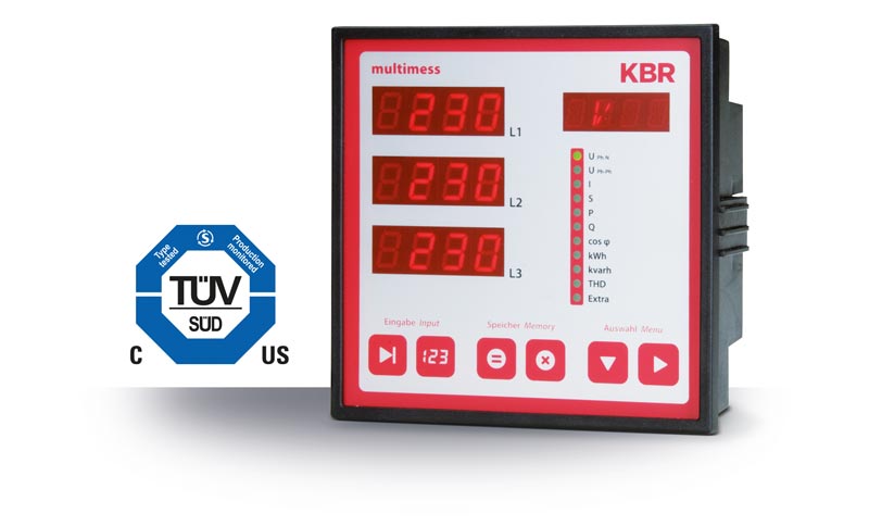
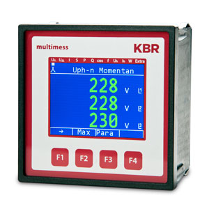
multimess F96-0-TFT-1DO-R1-US_-5 |
25951 |
25958 |
| [2] |
multimess F96-0-TFT-ESMS-1DO-R1-US_-5 |
25953 |
25963 |
| [3] |
multimess F96-2-TFT-ESMS-2RO1DO-R1-US_-5 |
25954 |
25959 |
| [4] |
multimess F96-2-TFT-ET-2RO1DO-R1-US_-5 |
25956 |
25961 |
| [5] |
multimess F96-2-TFT-MS-2RO1DO-R1-US_-5 |
25957 |
25962 |
| [6] |
multimess F96-2-TFT-MT-2RO1DO-R1-US_-5 |
25955 |
25960 |
| [7] |
multimess F96-2-TFT-ESET-2RO1DO-R1-GW-US_-5 |
25968 |
25970 |
1 US1 100 bis 240 V +/- 10% AC/DC 50/60 Hz, 8 VA
2 US5 22,5 bis 64 V +/- 10% AC/DC 50/60 Hz, 8 VA
| Input and output configuration |
| Device type |
[1] |
[2] |
[3] |
[4] |
[5] |
[6] |
[7] |
| Pulse output |
1 |
1 |
1 |
1 |
1 |
1 |
1 |
| Relay output |
– |
– |
2 |
2 |
2 |
2 |
2 |
| Interface |
– |
RS 485 |
RS 485 |
– |
RS 485 |
– |
RS 485 |
| – |
– |
– |
TCP/IP |
– |
TCP/IP |
TCP/IP |
| KBR eBus |
– |
Yes |
Yes |
– |
– |
– |
Yes |
| KBR eBus TCP |
– |
– |
– |
Yes |
– |
– |
Yes |
| Gateway function |
– |
– |
– |
– |
– |
– |
Yes |
| Modbus RTU/ASCI |
– |
Yes |
Yes |
– |
Yes |
– |
– |
| Modbus TCP |
– |
– |
– |
– |
– |
Yes |
– |
| Connection Rogowski tapes |
Yes |
Yes |
Yes |
Yes |
Yes |
Yes |
Yes |
| Memory |
– |
– |
Yes |
Yes |
Yes |
Yes |
Yes |
| Details, metrics and storage |
|
multimess F96-
[1] -0-TFT-1DO-R1-US_-5
[2] -0-TFT-ESMS-1DO-R1-US_-5 |
multimess F96-
[3] -2-TFT-ESMS-2RO1DO-R1-US_-5
[4] -2-TFT-ET-2RO1DO-R1-US_-5
[5] -2-TFT-MS-2RO1DO-R1-US_-5
[6] -2-TFT-MT-2RO1DO-R1-US_-5
[7] -2-TFT-ESET-2RO1DO-R1-GW-US_-5 |
| Metrics |
| Tension |
U Ph–N (L1 – L3) | U Ph-Ph |
U Ph–N (L1 – L3) | U Ph-Ph |
| Electricity |
I Ph (L1 – L3) |
I Ph (L1 – L3) |
| Average current value |
I Ph (L1 – L3) |
I Ph (L1 – L3) |
| Neutral conductor current |
IN | IN means |
IN | IN means |
| Apparent power |
S Ph (L1 – L3) | S total |
S Ph (L1 – L3) | S total |
| Active power |
P Ph (L1 – L3) | P total |
P Ph (L1 – L3) | P total |
| Q1 = fundamental reactive power |
Q1 (L1 – L3) | Q 1 total |
Q1 (L1 – L3) | Q 1 total |
| Frequency |
f network |
f network |
| Harmonics |
THD (L1 – L3) voltage |
THD (L1 – L3) voltage |
|
Id (L1 – L3) current |
Id (L1 – L3) current |
|
3. – 63. Harm. (L1 – L3) Tension |
3. – 63. Harm. (L1 – L3) Tension |
|
3. – 63. Harm. (L1 – L3) Electricity |
3. – 63. Harm. (L1 – L3) Electricity |
| Rotating field control: rotating field display in degrees |
Yes |
Yes |
| Performance factors |
Fundamental oscillation cosφ (L1 – L3) |
Fundamental oscillation cosφ (L1 – L3) |
|
Total power factor λ (L1 – L3) | λ total |
Total power factor λ (L1 – L3) | λ total |
| Electrical work |
Endless counter for active work P+ | P- |
Endless counter for active work P+ | P- |
|
Endless counter for blind work Q+ | Q- |
Endless counter for blind work Q+ | Q- |
| Tariff switchable |
HT / NT2 |
HT / NT |
| Memory |
| Load profile memory P total / Q total |
– |
P+ | Q+ (cumulative)3 |
|
– |
P- | Q- (cumulative)3 |
Storage duration of the load profiles
(with a 15 minute measurement period) |
– |
Ring memory for 366 days |
| Daytime, active and blind work |
– |
Annual working memory, daily values for active and reactive work |
| Split pointer function (min. / max.) |
yes1 |
Yes |
| Event memory |
– |
1500 events for logging tariff switching commands,
Error messages, etc. with date and time 3 |
| Operational diary |
– |
500 entries with date and time |
1 Without storage and timestamps
2 Switching via eBus
3 Cannot be read via Modbus
Let your creativity run wild, use our color configurator. It should help you find the right colors for your multimess F96-xxx-5.
Click here for the color configurator