Search
Energy optimization expansion module for long transmission distances

multisio D6-4RO-ISO

Signal acquisition and processing

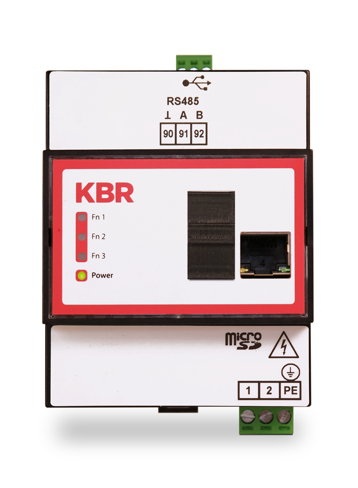
Additional module for the multimax energy optimization system

multisio D6 4RO ISO

The multisio D6-4RO-ISO-1 with eBus supports 4 potential-free relay outputs (changeover relays).

The relay outputs are used to control contactors of loads or other systems.

The module can be addressed by a master device (multimax D6-xxx-5, multisio D6-xxx-7 or higher, or PC with visual energy via multigate ESBS) via the module bus interface.

Extended module bus up to 1000 m without bus amplifier, with suitable installation.

The extended module bus interface (RS 485 serial) also functions as a gateway (conversion from module bus RJ12 to eBus (BSES)). Requirement: Module bus input via RJ12 plug, eBus output via terminals 93, 94 and 95.

Highlights
Technical data
  • Extended module bus
  • 4RO-ISO with integrated power supply unit
  • Relay with changeover contact
  • Ideal for use in installation distribution boards
  • Compact design
  • Modularly expandable

Technical data of the multisio D6-ESBS-4RO-ISO

multiso D6-ESBS-4RO-ISO Article no. 24444
Hardware inputs
Power supply Via module bus: 24VDC / max. 3W
Connection: Modular plug socket RJ12:6P6C
Via mains connection: Ph-N 100V – 240V +/-10% 50Hz/60 Hz/DC,Ph-N 100V – 240V +/-10% 50Hz/60 Hz/DC,max. 25 VA, 13W
Terminal 1 Phase (+)
Terminal 2 Neutral conductor (-)
Terminal 3 PE
Connecting elements Plug-in terminals
Permissible cross-section of the connecting cables Power supply 2.5 mm2
Control voltage input Fuse protection max. 1 A slow, max. C2 Automatic machine
Mains isolating device approved to UL/IEC
Hardware outputsa
Module bus interface Serial interface RS485
Module bus connection RJ12 for prefabricated
KBR – System cable, max. Length 30 m with suitable installation.
Maximum DC output power 7 W
Transmission speed 38400 Bps
Bus protocol KBR module bus/eBus
Extended module bus Connection eBus via 3-pole plug-in terminal

Terminal 93 (⊥)
Terminal 94 (A)
Terminal 95 (B)

Bus cable, up to 1000 m (for more information, see KBR eBus installation guideline)
4 relay outputs 2 plug-in terminals, 6-pole each
Changeover relay A1: Terminal 41 NO contact relay 1
Changeover relay A1: Terminal 45 Common connection relay 1
Changeover relay A1: Terminal ¬ 41 (inverse) NC contact relay 1
Changeover relay A2: Terminal 42 NO contact relay 2
Changeover relay A2: Terminal 46 Common connection relay 2
Changeover relay A2: Terminal ¬ 42 (inverse) NC contact relay 2
Changeover relay A3: Terminal 43 NO contact relay 3
Changeover relay A3: Terminal 43 Common connection relay 3
Changeover relay A3: Terminal ¬ 43 (inverse) NC contact relay 3
Changeover relay A4: Terminal 44 NO contact relay 4
Changeover relay A4: Terminal 48 Common connection relay 4
Changeover relay A4: Terminal ¬ 44 (inverse) NC contact relay 4
Contact load capacity 500VA, 2A, 250V 50/60Hz AC each
Overvoltage category CAT II
Display LED 4x message
1x power indicator
Control unit DIP switch 1x 8-way, for manual operation
1x 4-gang, for bus termination1x 4-gang, for bus termination serial connection RS485
Button Scan button (module bus)
Mechanical data
DIN rail device Housing dimension 90 x 108 x 61 mm (H x W x D)
Mounting type Wall mounting on standard rail; 7.5 mm deep, in accordance with DIN EN 50022; suitable for distribution board installation
Weight approx. 650g
Ambient conditions / Electrical safety
Ambient conditions Standards DIN EN 60721-3-3/A2: 1997-07; 3K5+3Z11; (IEC721-3-3; 3K5+3Z11)
Operating temperature K55 (-5°C …. +55°C)
Air humidity 5 % … 95 %, non-condensing
Storage temperature K55 (-25°C …. +70°C)
Operating height 0….2000m above sea level
Electrical safety Standards DIN EN 61010-1: 2011-07
Protection class I
Overvoltage category CAT III
Rated impulse voltage 4kV
Protection class Standards IP20 according to DIN EN 60529: 2014-09
EMC Standards DIN EN 61000-6-2:2006-03 + Corrigendum 1:2011-03
DIN EN 61000-6-3:2011-09 + Corrigendum 1:2012-11
DIN EN 61326-1:2013-07
Fittingly:
igw-frontal_

Extension module for controllable loads

multisio-d6_multisio-tft_buehne_

Storage center multisio system

KBR
Support Team

We are happy to arrange
the contact to our
references and are available for
available for an interview.

Just get in touch with us.
Phone: +49 9122 6373-0
E-mail: info@kbr.de

Tablet mit Screenshot

Download

More information (brochures, user manuals, etc.) under download.