SSTB p = 5.5, 7 or 8 %
SSTB p = 12.5 or 14 % |
| Rated voltage | frequency: |
Un = 400 V | 50 Hz |
| Maximum permissible operating voltage: |
Un = 400 V ± 10 % |
| Maximum permissible operating current: |
1.3 xIn permanent |
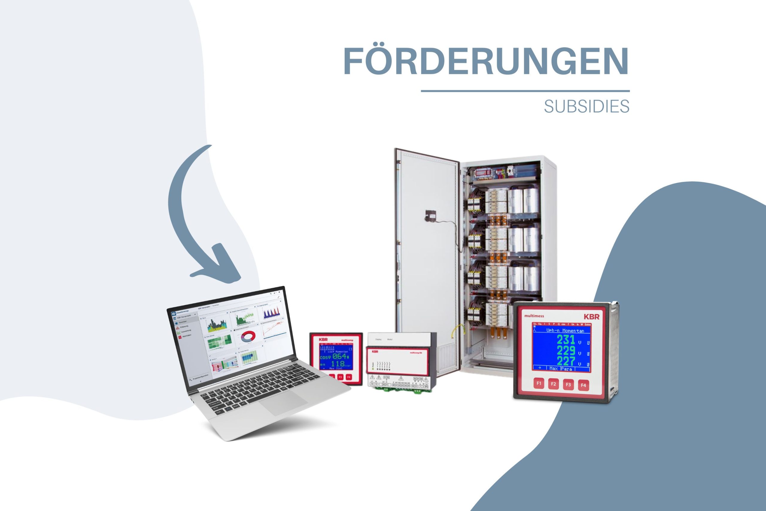
| Reactive power controller: |
multicomp F144-12DO, with 12 optocouplers – outputs for dynamic compensation systems |
| Current transformer connection: |
1 A and 5 A |
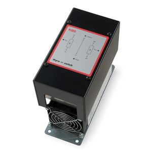
| Switching element: |
Thyristors |
| Control voltage: |
DC control: Utax = 10 – 30 V
AC control:Utax = 230 V, 50/60 Hz
Control via reactive power controller or directly via PLC or process controller |
| >>> Control voltage transformer required for deviating operating voltage |
| Switching delay: |
DC control: 1 – 15 ms, dynamic controller required
AC control: 10 – 25 ms with direct control
500 ms with control via standard reactive power controller |
| Capacitors: |
Low-loss multicond UHPC power capacitors, MTK technology |
| Nominal capacitor voltage: |
UBem. = 525 V |
| Discharge of the capacitors: |
The EPL technology means that no unloading time is required during operation.
Discharge resistors t < 180 s
no discharge throttling possible. |
| Filter circuit chokes: |
Linear filter circuit chokes to avoid resonances in networks with harmonics,
Built-in temperature monitoring |
| Throttling factors: |
p = 5.5, 7 or 8 % ; p = 12.5 or 14 % |
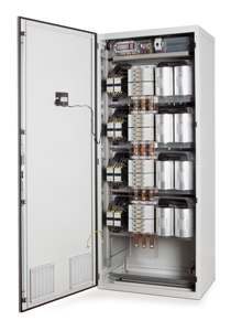
| Housing design: |
Sheet steel cabinet, interior and exterior paint finish RAL 7035 (other paint finishes on request),
Galvanized module panels, door hinge left (optionally right), bottom feed (on request from above), protection class I |
| Protection class: |
IP 20 (IP 54 on request), the components used comply with DGUV regulation 2 (on EN “DGUV rule 3”) |
| Ambient temperatures: |
+ 40 °C Maximum value, short-term
+ 35 °C in 24-hour average
+ 20 °C annual average
– 10 °C Lowest value |
| Ventilation: |
Built-in roof ventilator, temperature-controlled |
| Protection: |
Group fuse protection with NH fuses and fuse bases
(NH isolator on request) |